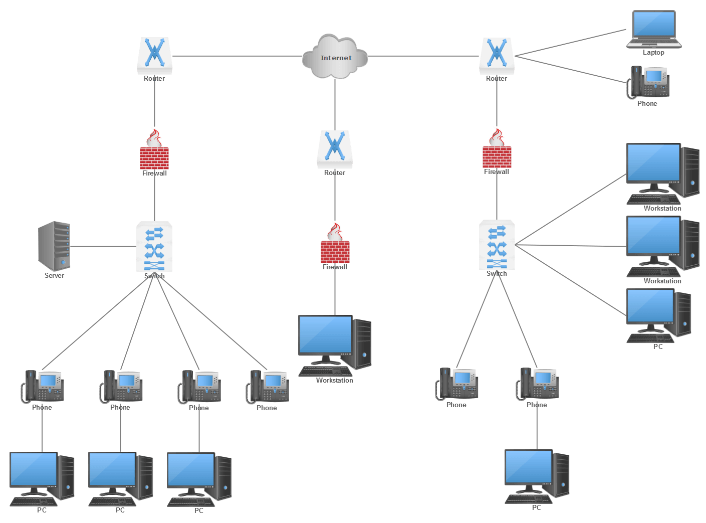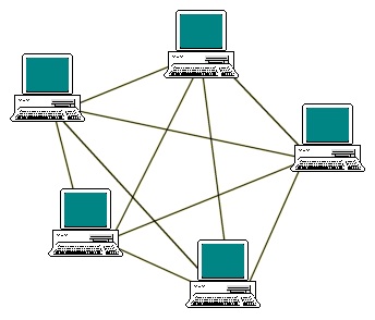
A network made up by two or more different topologies. Because there is no single source of failure, it's safe and reliable however, the complexity of it results in high costs and long configuring. A secure topology in which the devices are connected and data is transferred via routing (sent the most efficient distance) and flooding (sent to all devices). It's reliable in the event that the central hub fails however it could be costly to set up and use. All data flows through the central hub that connects to the other devices in the network. A common topology is used for larger networks. Terminators aren't necessary, but one failure can disrupt the entire network and can be difficult to fix. The network may run more efficiently than in a bus topology. It's easy and economical but it can be prone to interruptions for all devices, as well as complex troubleshooting. Each device is connected to the same cable, with two ends. It's the structure of the internal communications between devices.ĭifferent topologies have different effects on stability and performance. It is defined by the protocol for the network and defines how data moves across the network. Logical Topology is the method by which the logical flow of data within a network occurs. It covers the physical layout of computers, nodes and cables, device locations, and installation of code. Physical topology is the arrangement of other devices and devices within the computer network. Topologies come in two varieties comprising physical topology as well as logical topology. The term "physical topology" should not be confused with the logical one which is utilized to transmit information between workstations. Physical topology in networks refers to the arrangement of computers, cables as well as other devices. The logical topology of the network and the physical topology of the network. The diagram of the network topology is presented in two different ways. In terms of the word, the network topology is the way in which the components of a network that are responsible for the connection between the devices of a network are arranged to prevent errors, provide greater bandwidth, secure the network, etc. Network topology is the arrangement of links and nodes within a specific mechanism and plan. In order to represent any one or more of the three layers of a network (physical, data link, and network) in accordance with the Open Systems Interconnection (OSI) model, also called the layers of media, they create Network diagrams. Network topology diagrams are an image representation of a network's devices connections and paths which allows you to see how the devices are connected and how they interact with each other. Level 2 is the level that shows the data links between nodes while level 1 shows the physical layout. Also called “the network layer" 元 is an abstraction layer that handles forwarding packets via intermediate routers. Within the Open Systems Interconnection (OSI) model, logical diagrams of networks correspond to the information within Layer 3. Thus, logical diagrams usually show the subnets (including the VLAN's ID, masks, and addresses) as well as network devices such as routers as well as firewalls and routing protocols. A logical network diagram explains how information flows within networks. For instance, a diagram for the LAN may show all the IP addresses for the computers and the diagram of the man (metropolitan region network) might represent zones or buildings that have a single node.Ī diagram of networks can be either logical or physical. The diagram of a network shows the components of a neighborhood region (LAN): (LAN):īased on the scope and intent, a network flow diagram can include a lot of information or simply provide an overview. It shows the various components that comprise the network and the way they work together, such as hubs, routers, devices, and firewalls, among others. Network diagrams are an illustration of a telecommunications or computer network.


Network Diagram: An Essential Tool for Effective Time Management


 0 kommentar(er)
